
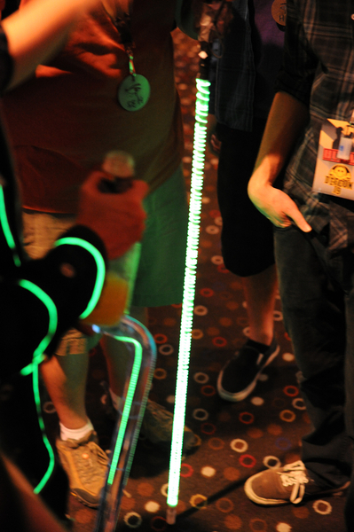
As part of my Defcon 19 costume, I decided to upgrade my goggles worn on the 1.0 version from DC18. ORiginally I had installed green LED's in the airvents and hooked them up to an arduino pro mini. They simply pulsed a green glow across my eyes. ASTcell took a great pic. They were effective for what I could build on my In-laws couch in the week between HOPE and Defcon.
For this year I wanted to go bigger and creepier. Shortly after Defcon and right before Haloween 2010, I came across a post on the MAKE blog about a guy who installed a couple OLED screens in some welding goggles playing an animation of eyeballs, along with a respirator, it made for a very awesomely creepy costume. According to the post, he lives in Edmonton and after a few emails, it turns out Donald had just found out about ENTS, our local hackerspace and has since become a great member.
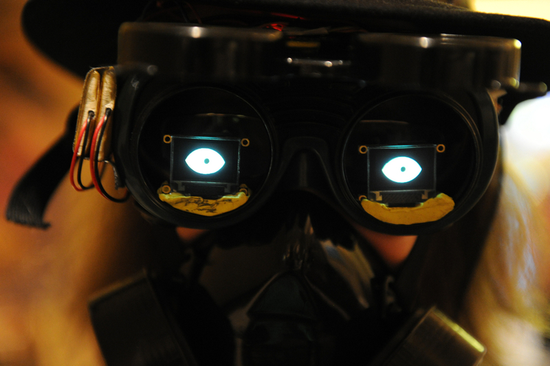
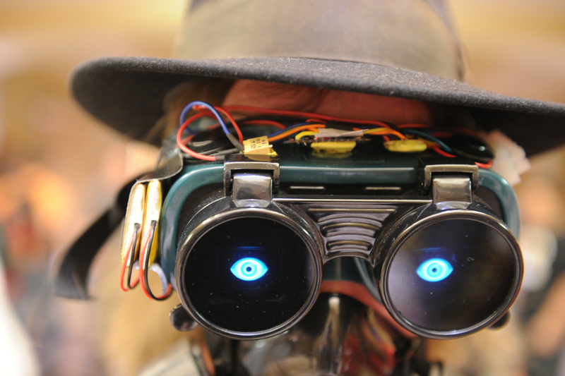
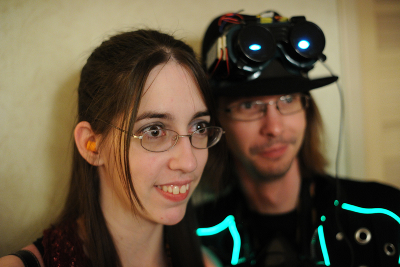
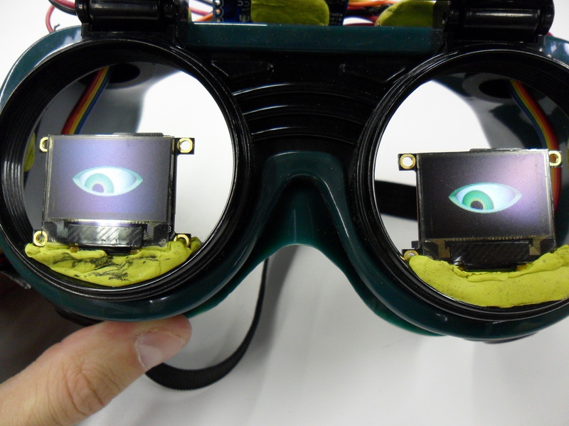
I decided to take a page from Donalds creation and use the OLED screens in my goggles and add some extra functionality. I ordered the 0.96" OLED serial screens from Sparkfun (as I do for everything. I think I owe sparkfun my first born son or something by now).
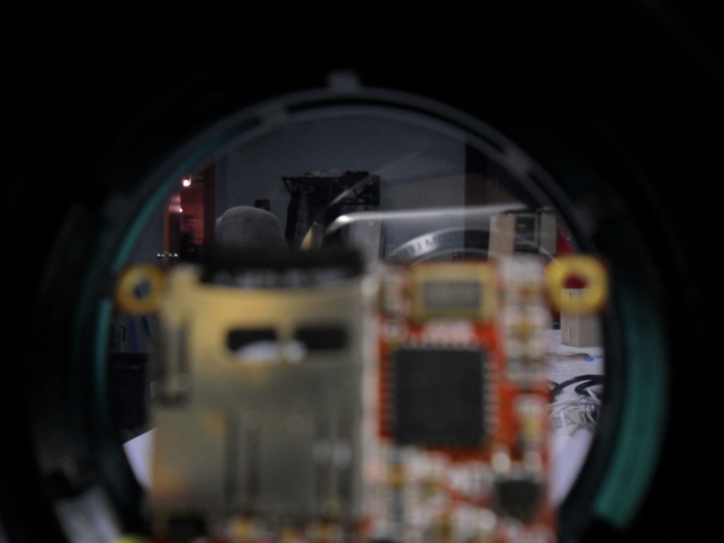
I ordered the screens in November and through the holidays I played around with them to familiarize myself with thier control. The screens are brilliant for this application. They run animations off of microSD cards on the back of the screens which means that the host controller does not have the overhead of running the animation. You load the cards with your images or movie files with the windows application and it adjusts the resolution and encodes them to the cards. The other thing the application does is spit out a text file with the nessecary strings and memory addresses to call the images via serial from the microcontroller. The controller can call the images or movies but is not responsible for the actual processing. Just send out a serial command and your good. This also means that you can have it respond to events (button presses, etc) which I wanted to utilize to add to the creep show. In any event, the screens are small enough and the goggles sit low enough, that I could look over the screens and still see where I was going.
I got the screens running a looped animation of eyes looking left and right which was pretty damn effective. Donald sent me his sample code for the OLED screens and after a while, I got it sorted out and able to address the screens over serial. My sample was some static images that took input from an accelerometer to change the image depending on direction of tilt. It worked great on a single screen. To get both screens working it was nessecary to only hook up the TX line from the Arduino to the second screen since really it doesnt need to talk back and having two screens talk gets wierd. There is probobly a better way, but not that I cared to explore.
A couple more sparkfun orders got me all the parts and cabling I needed to build the thing and assembly started.
Alot of snags were hit. My original plan was to have the screens switch to looking left or right when an accelerometer detected me turning my head left or right. While I had prototyped this with static images, it turns out there is no easy way 2 weeks before hand to have a looped animation run and then interrupt it to do the left or right animation, then back to the main loop. If there is, it would take a lot more work on the arduino side of things to coordinate. I'm planning on investigating this just for my own amusement.
In the end I had to ditch the accelerometer and the plan for serial control of the screens. The arduino is essentially just a power source for the screens at the moment, but even with just a looped animation, the effect was amazing and creeped alot of people out.
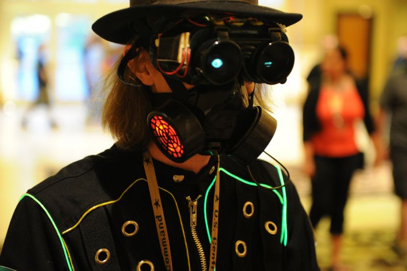
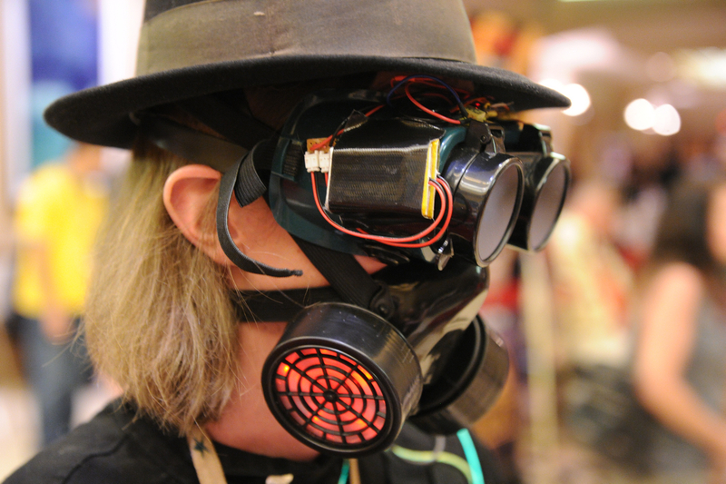
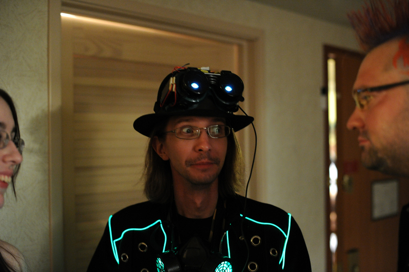
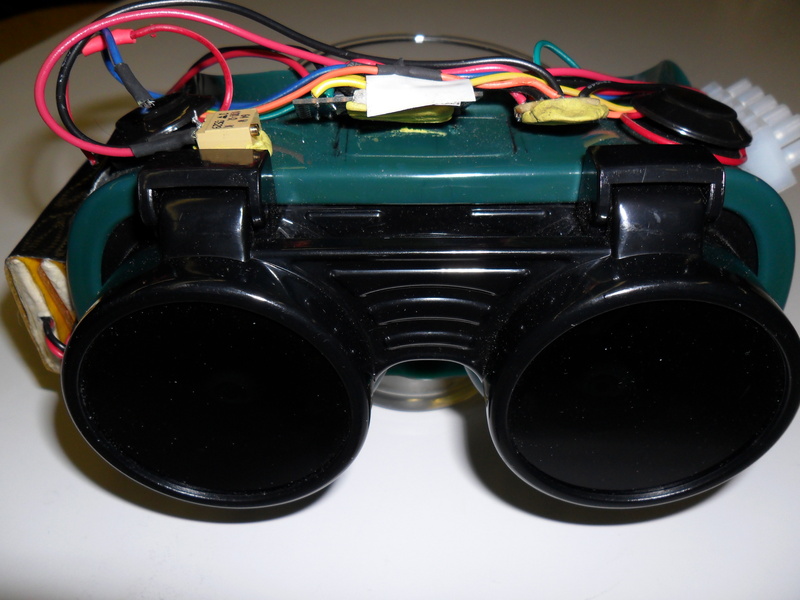
The cabling harness was run out of the air vents to the arduino on the top of the mask. I went for the wiring to be external since I wanted to wear the goggles and having all the wires and controller inside would make vision impossible. The whole thing was wired up and worked great.
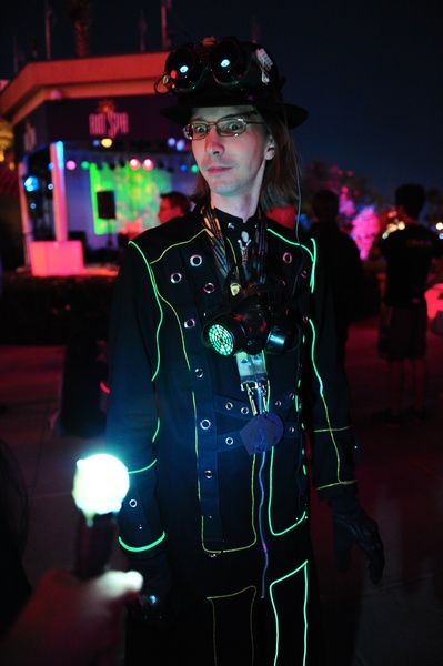
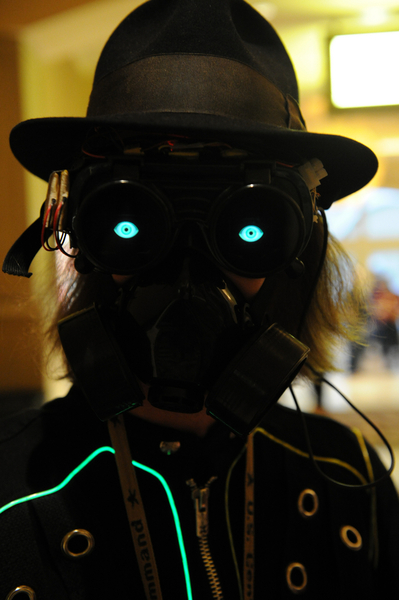
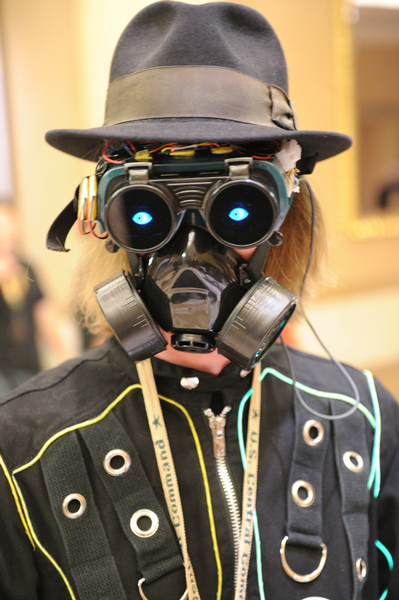
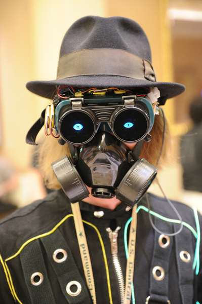
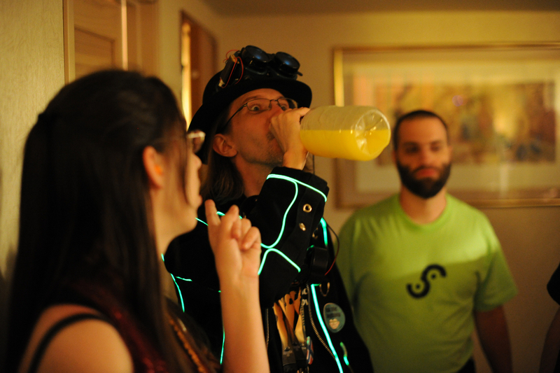
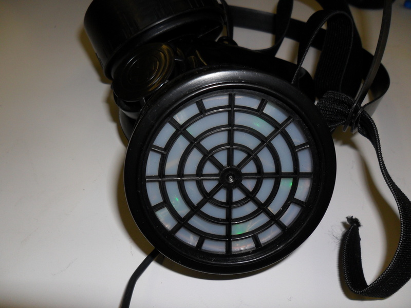
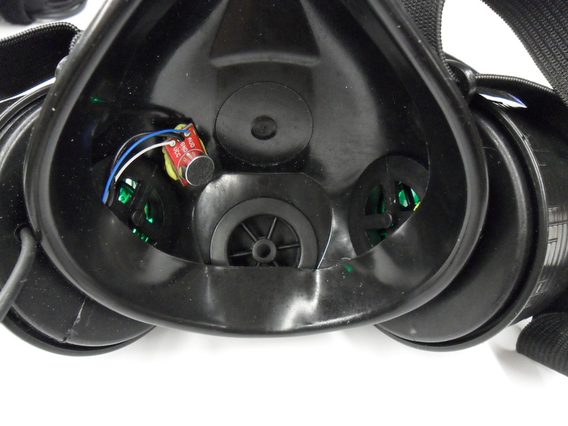
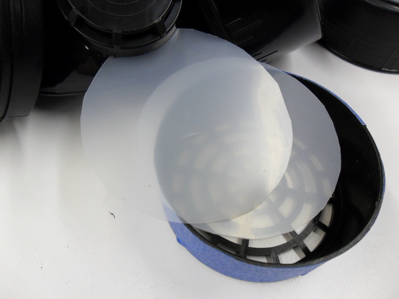
The lenses of the goggles were a small problem. The green tinted glass of the welding goggles blocked the green of the animation I wanted to use and was generally very dark. The glass and the clear plastic covers are held in place with screw in rings from the back of the goggles. I removed the green glass on the flip down portion and completely removed the clear internal ones. I went to an auto tinting place and after a few wierd looks, got a chunk of off cut auto tinting film that blocked enough light that you could'nt see my eyes, but not so much or was a shade that blocked the screens.
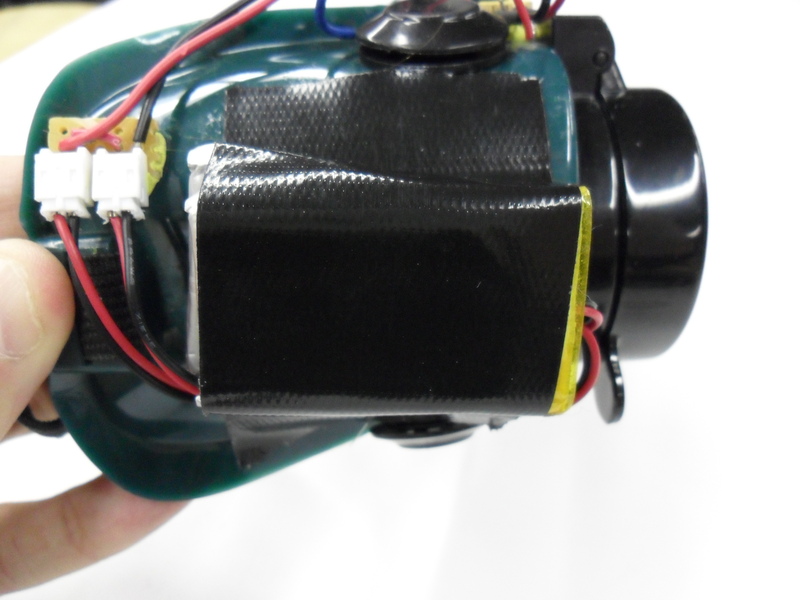
The power source changed a few times. Originally it was going to be 9v batteries but that changed when I did the math and measured the current draw of the screens and mask. Each screen was 40ma and the mask was about 100ma for the mic and 10 LED's. Add some overhead for the arduino and you are at 200ma draw. The 9v batteries typically have about 500-600 mah of power, so I'd be changing batteries every 2.5 hours or less once the voltage dropped. Also include waste from the voltage conversion from 9v to 5v on the arduino. I ended up using two Li-Po batteries I had from the coat last year, a 900mah and a 1000mah (upgraded the coat to a 2000mah battery). Both batteries were 3.7 volts, so hooked in series they gave me about 7.4 volts and with less of a drop from the converter, plus the addtional capacity, it would last me through a night of partying, however the recharge time is about 8 hours, so a bit of a pain if I stumble in drunk and forget to charge my costume (there's a statement).
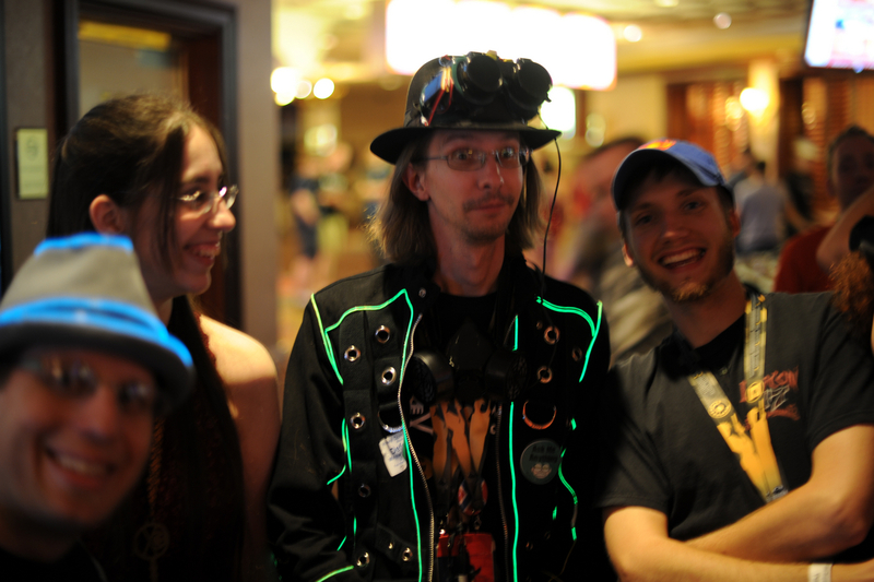
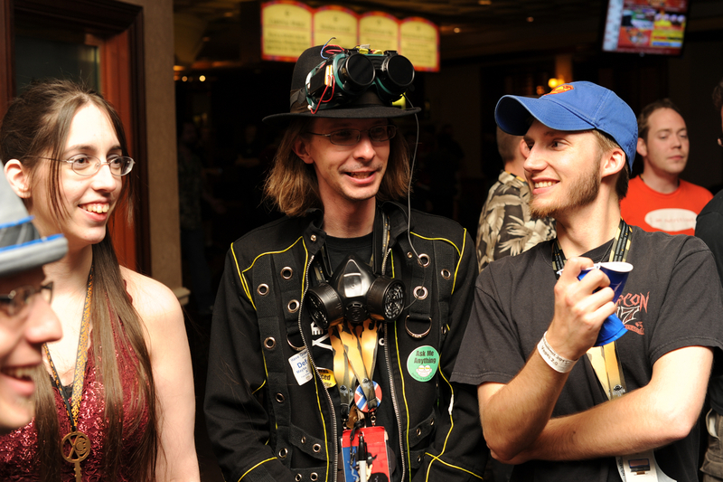
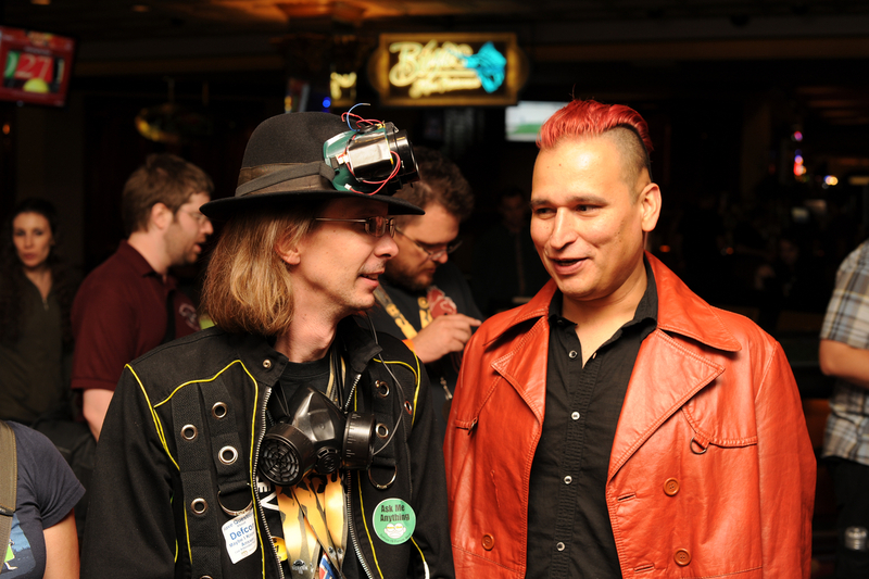
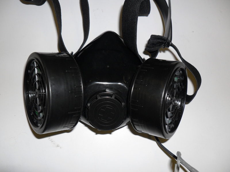
The respirator idea was born out of too many post apocalyptic movies and video games and my general desire to be a super villian, most of which have some sort of breathing apperatus on thier face that does something cool. In my case, I wanted something that would light up and indicate that I was speaking or some other level of interactivity.
I originally had intended to use a proper safety respirator but the one I bought had very tightly sealed canisters that would have been a bitch to add anything to. I ended up finding a costume respirator from a military surplus place which had no filter elements in the canisters and they come apart easily.
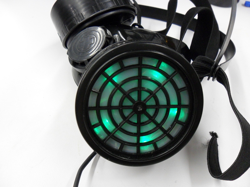
I ended up with, yet more sparkfun orders, getting a Electret Microphone breakout that suited my needs. Talking with Donald at the hackerspace, he pointed out the difficulties with this particular microphone since it spits out an analog wave form of values that are not indicative of the volume the microphone detects. It's baseline is a value of 500 but indicates both the highs and lows of the audio wave form, so a half range sound would output values of 750 and/or 250 depending on where on the audio wave the arduino takes the sample. For applications that need an absolute value of volume (sound pressure) this really sucks. For my application however, I only needed to know when some threshold was reached, such as when I was speaking as opposed to not speaking.
I prototyped using RGB LED's, using only the Red and Green elements where green is the standard, switching to RED when I spoke. After some prototyping and tinkering I had the circut built up and code made. I had to do some pretty awful things to the incoming signal from the microphone to get a realitivly stable value to use. I however had a small flash of brilliance and added a trim pot to adjust the value of my threshold for changing color so that I could adjust easily for loud parties and such. Worked out better than I had planned since it would involve me handing someone a screwdriver and having them turn a screw on my head.
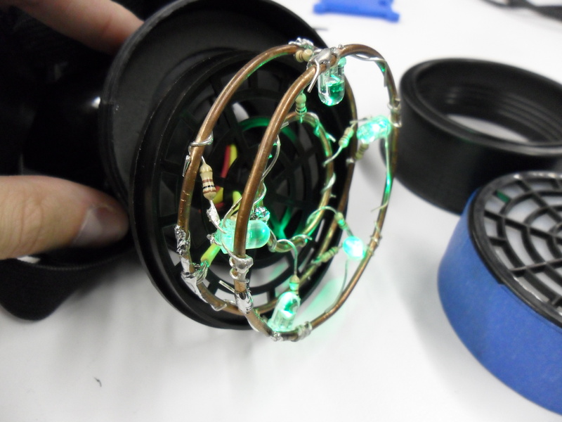
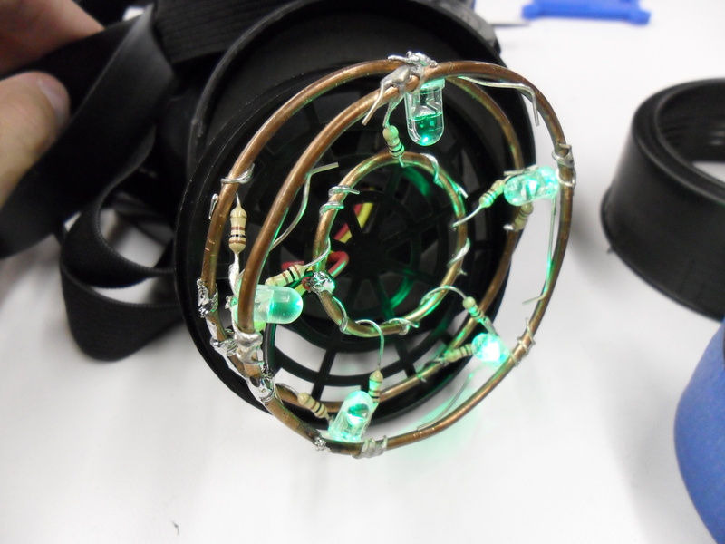
The actual installation of the LED's is something that I credit to Jesse at our hackerspace. I had originally thought of glueing the LED's in place and running the wires all over, but this was problematic. Jesse suggested using a common ground rail to mount things to. I took this and ran with it. Using a heavy guage copper ground wire I scavenged from the spaces vast reservoirs of crap, I made a ring that fit in the bottom of the canister. This was the ground rail for the LEDS and the ground pin on the LEDs were soldered around the ring, LED's pointing towards the middle. Another ring of the same size was made as a common RED anode with the resistors holding the two apart and acting as a bit of structure. Another, smaller ring was made for the inside and similarly connected and supported, free floating in the middle of the larger rings to be the common anode for the green element of the LEDs. This works freaking brilliantly.
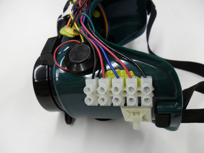
The whole thing needed 5 wires, Ground, Red, Green, 5v (for mic) and an analog line for the mic. The only thin wire I could find with 5 wires was a PS2 mouse cable. In retrospect I would have liked to have used a second microcontroller to run the mask, but utility and budget meant I had to use the Arduino on the goggles. Additionally, there was very little room in which to mount anything else inside the mask, so unless I built up a attiny or something, but that's beyond my skill at the moment.
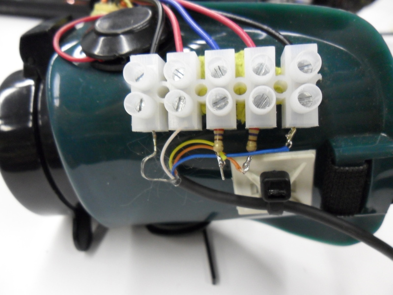
The mic was mounted in a small corner of the mask. The wires were run out a small hole in the back of one of the canisters to the side of the mask. I used a screw terminal block to connect the mask to the arduino since I wanted to be able to disconnect the mask from the goggles on occasion and a pin based connector would be too bulky.
The main problem I had was how to mount all the various bits onto the mask and goggles, specifically the OLED screens since they are square pegs having to go into a round hole. The neatest solutions can be found in the strangest places. I went to Michaels to see what sort of glues for plastics they may have and found this stuff, called Handi-Tak It's a sticky putty that is used for hanging posters and stuff. It's non-conductive and doesnt dry out. It also sticks to the plastic bits of the mask really well. The best use was to mount the screens since the putty could adapt the round eye piece to the flat screen and hold it in place very solidly. I was a bit worried about rolling through an airport with electronics pressed into putty, but no one said anything, so I guess they did'nt see anything.
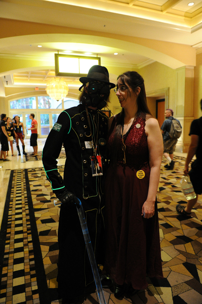
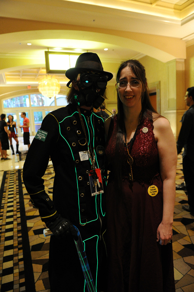
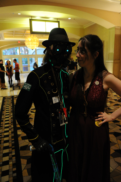
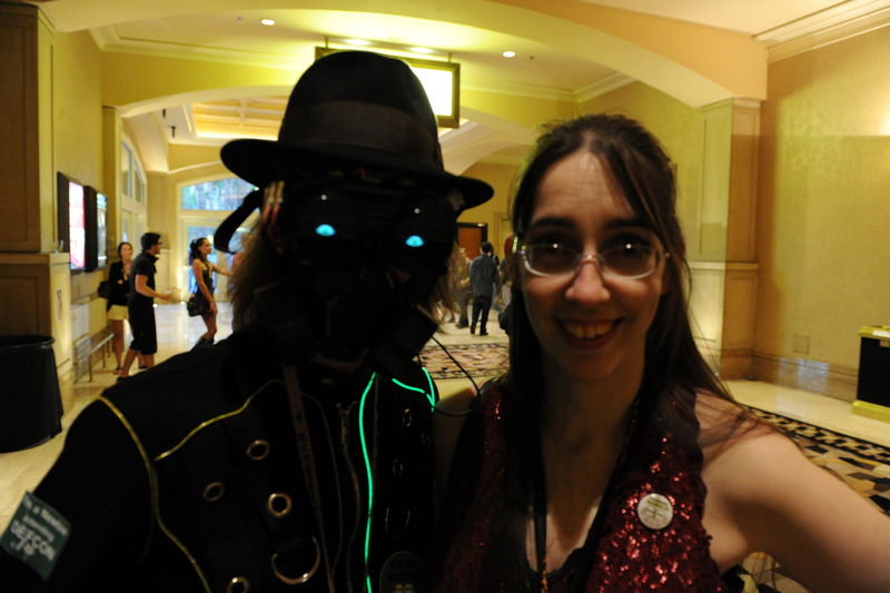
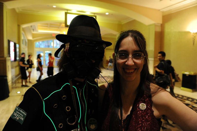
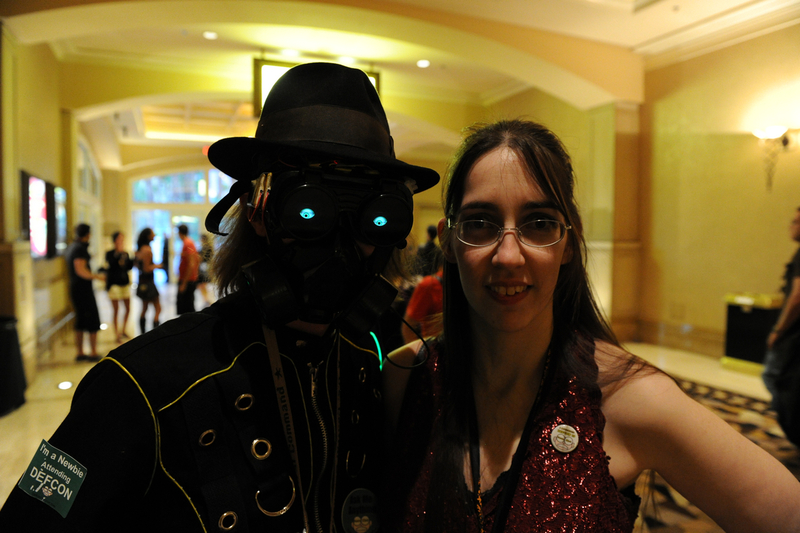
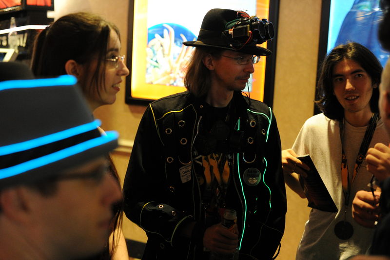
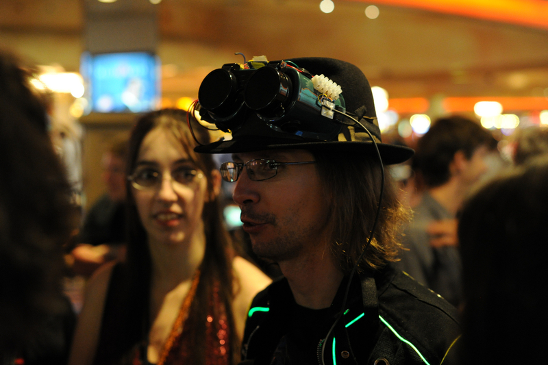
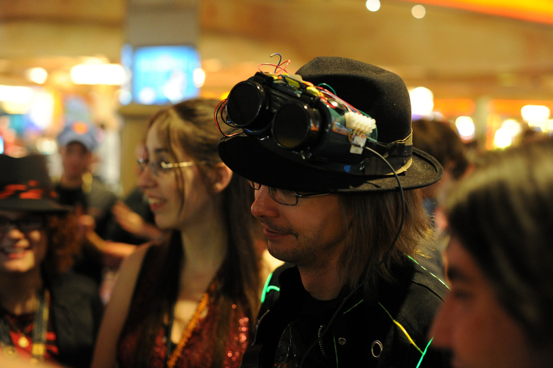
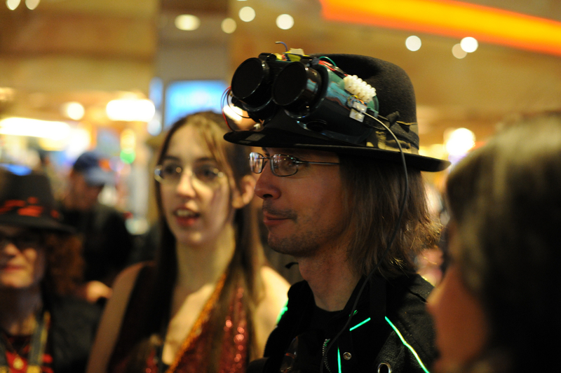
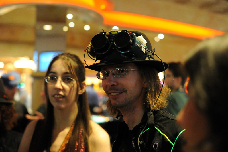
The mask and goggles rocked the con. The whole ensemble worked well together and blew alot of minds. The whole supervillan thing with the coat, and the cane and the mask worked but was very hot to wear, so for much of the night, I wore the goggles on my hat and the mask hanging around my neck. It still looked creepy since the eyes continued to look around while on my hat.
OK, dont laugh at my code, it sucks, but it worked. I'm just learning and learning is full of mistakes and ineffeciencies.
uOLED.zip - Sample code from Donald at aeinnovations which has the libraries and sample code I used to get the serial oled screens talking to the arduino. These libraries are needed for any of the other oled screen code belowoled_test_accel.pde - Test code for the oled screens changing images based on external event (accelerometer tilt)
voice_test_4.pde - Code for the voice controlled LED respirator, using a sparkfun electet microphone
 |
 |
 |
 |
 |
 |
 |
 |
 |
|
 |
 |
 |
 |
 |
 |
 |
|
 |
 |
 |
 |
 |
 |
 |
 |
 |
 |
 |
 |
 |
 |
 |
 |
 |
 |
 |
 |
 |
 |
 |
 |
 |
 |
 |
 |
 |
 |
 |
 |
 |
 |